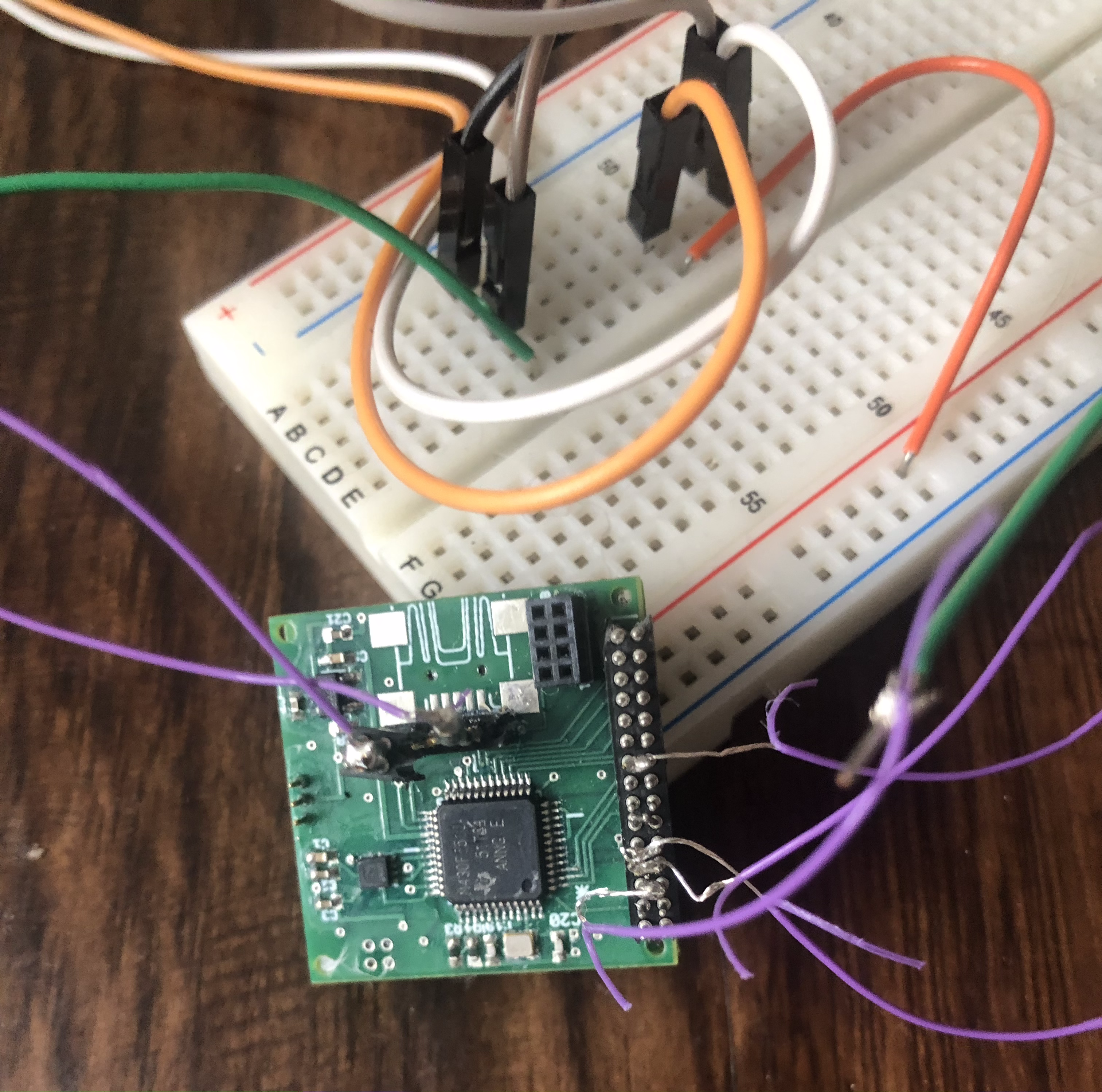
Antenna design and communication module architecture for fully implantable micro ECoG Device
Fall 2022
This is my part of the group final project for the Implantable Medical Devices (IMD) class that I took in Fall 2022 (EE 597) with Dr. Mehdi Kiani.
The objective is to design and simulate the core components for a design of a fully implantable wireless micro Electrocorticography (ECoG) device. The device aims to solve common ECoG disadvantages such as bulkiness, high invasiveness and a need for cables and meet clinical constraints such as ease of implantation, longevity, safety and small size
![]()
My focus and efforts were mostly regarding the wireless communication system between the implanted chip and the outside chip.
Antenna design
The antenna is a crucial component for having efficient data transmission without loss and use of cables and permitting the full implantability of the device.
When designing an antenna it is important to consider several aspects:
Because of these reasons we decided to use silver since it is a highly conductive and biocompatible material.
![Implanted antenna design]()
![S parameter in free space and through head of the implanted antenna]()
![Skin level antenna design]()
![S parameter in free space and through head of the skin antenna]()
![External antenna design]()
![S parameter in free space and through head of the external antenna]()
Simulink Antenna Toolbox was used to design the three antennas shown in figure 5.1: one implanted 1 cm deep, between the skull and the dura, one applied at skin level to act as a middle coil and a third applied at 1 cm from the skin to deliver energy to the other two coils and connected to an external IC.
![Electric field intensity of the system through the simulated layers of the head]()
![Electric field intensity through the tissue from the implanted antenna]()
![Electric field intensity through the tissue from the skin antenna]()
![Electric field intensity through the tissue from the external antenna]()
The objective is to design and simulate the core components for a design of a fully implantable wireless micro Electrocorticography (ECoG) device. The device aims to solve common ECoG disadvantages such as bulkiness, high invasiveness and a need for cables and meet clinical constraints such as ease of implantation, longevity, safety and small size
Structure
We designed and simulated the main elements of an IC for ECoG recording using a 3-coils power transfer module, a telescopic cascode amplifier, a clock generator for independent control over multiple amplifiers and a set of antennas for wireless communication with minimal occupied area and specific absorption rate (SAR).
My focus and efforts were mostly regarding the wireless communication system between the implanted chip and the outside chip.
Antenna design
The antenna is a crucial component for having efficient data transmission without loss and use of cables and permitting the full implantability of the device.When designing an antenna it is important to consider several aspects:
- the radio wave propagation can be affected by the diverse layers of tissue present by changing the speed and attenuating the signal.
- the wavelength is affected by the conductivity of the medium, the more conductive, the more the effective wavelength is reduced, permitting more miniaturization.
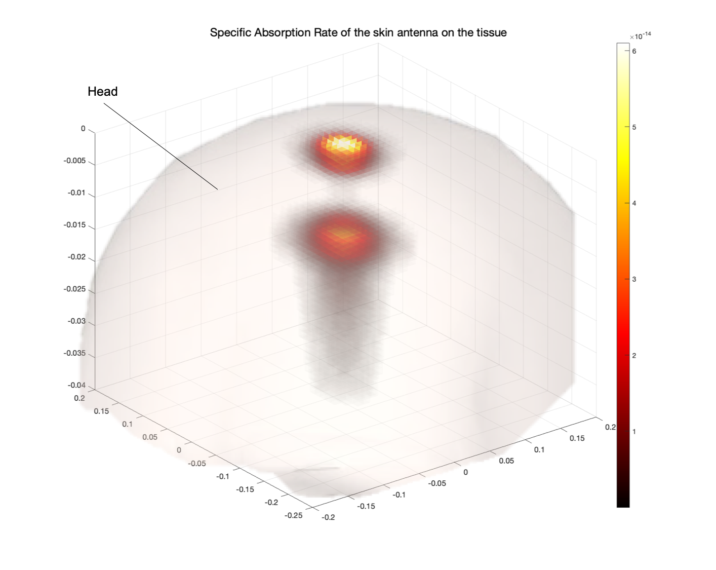
- Specific absorption rate (SAR): radio frequencies and inductive coupling can be dangerous if too much energy is released to the surrounding environment, causing tissue heating and neuronal activation. This value should be <1.6 W/kg according to FCC regulations.
- Biocompatible coating for the antenna: to prevent direct contact from the tissue and reduce coupling with it, the antenna should be coated with a biocompatible material (insulating dielectrics usually)
- Powering: Wireless inductive coupling will be used for powering the device and backscattering will be the method for communication.
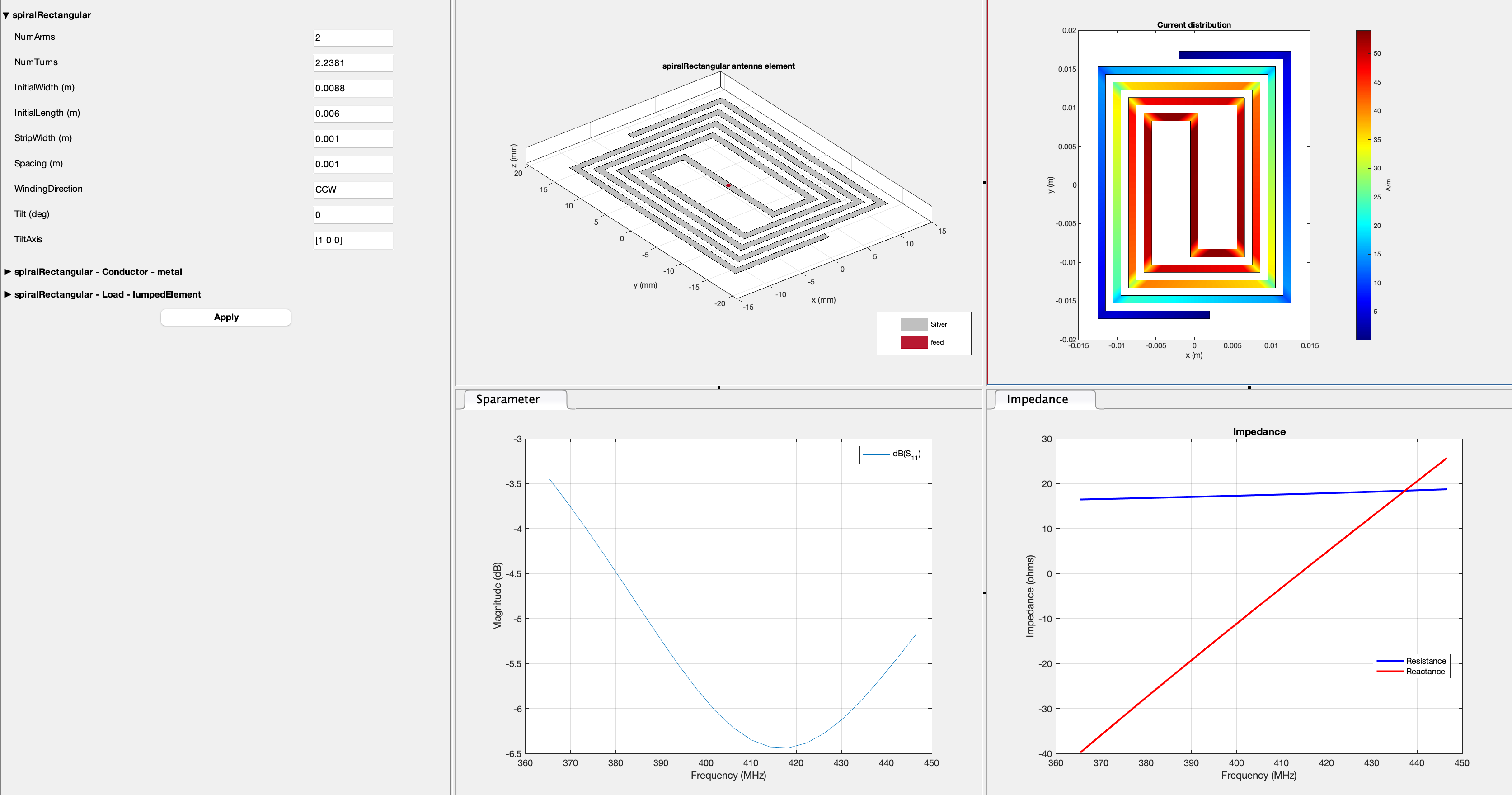
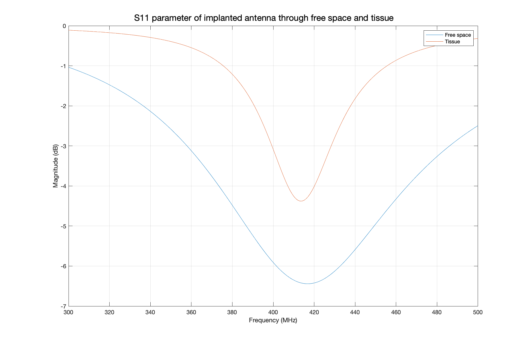

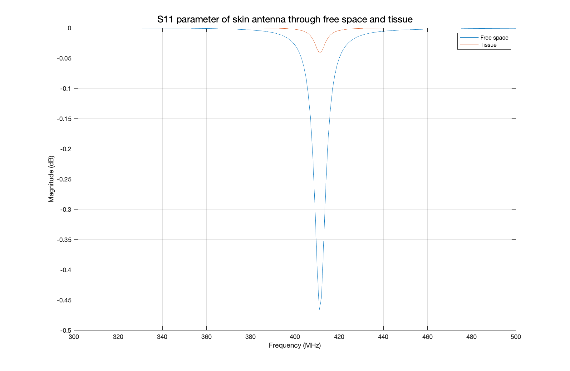

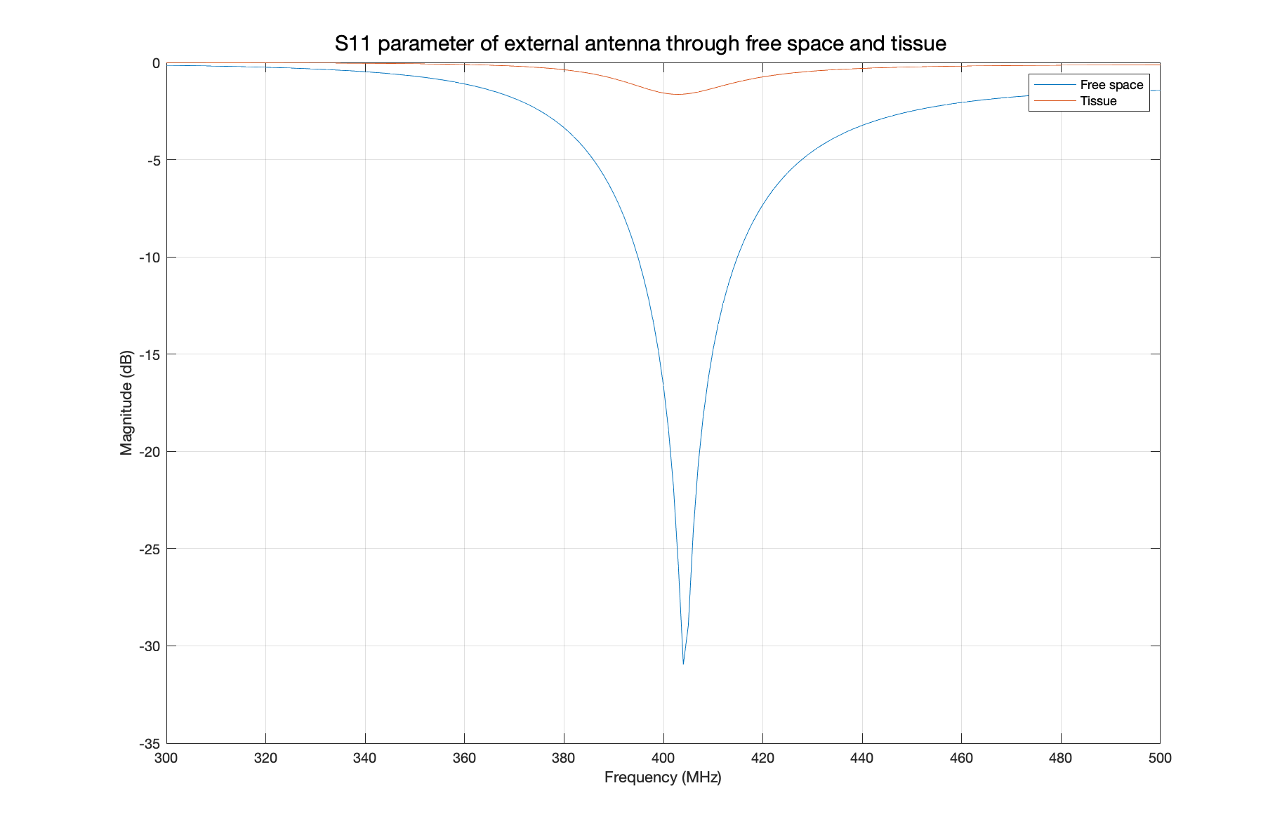
Simulink Antenna Toolbox was used to design the three antennas shown in figure 5.1: one implanted 1 cm deep, between the skull and the dura, one applied at skin level to act as a middle coil and a third applied at 1 cm from the skin to deliver energy to the other two coils and connected to an external IC.
Electric Field
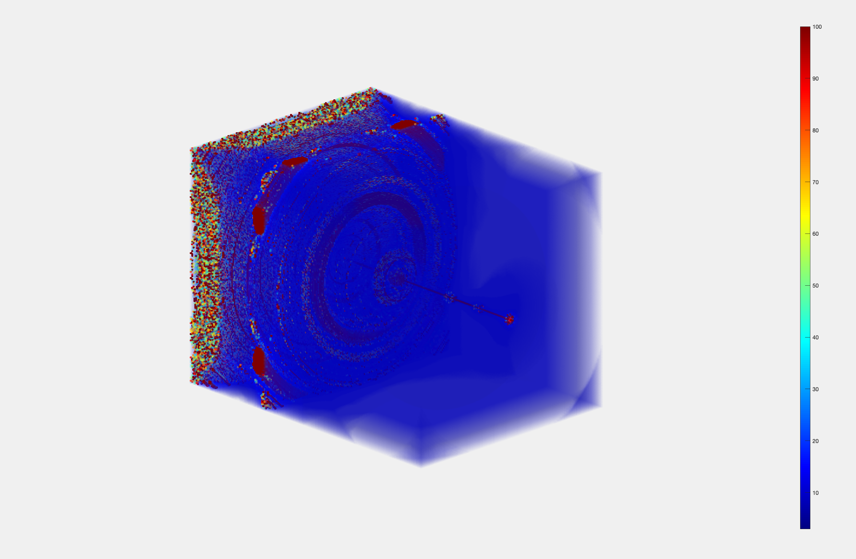
To simulate the propagation of the electric field through the brain, I used MATLAB to recreate a human head modelled as planar layers with different densities and conductivities. The antenna shape was chosen to be spiral shaped with one or two arms depending on the size and s11 parameter optimization to resonate at 406 MHz.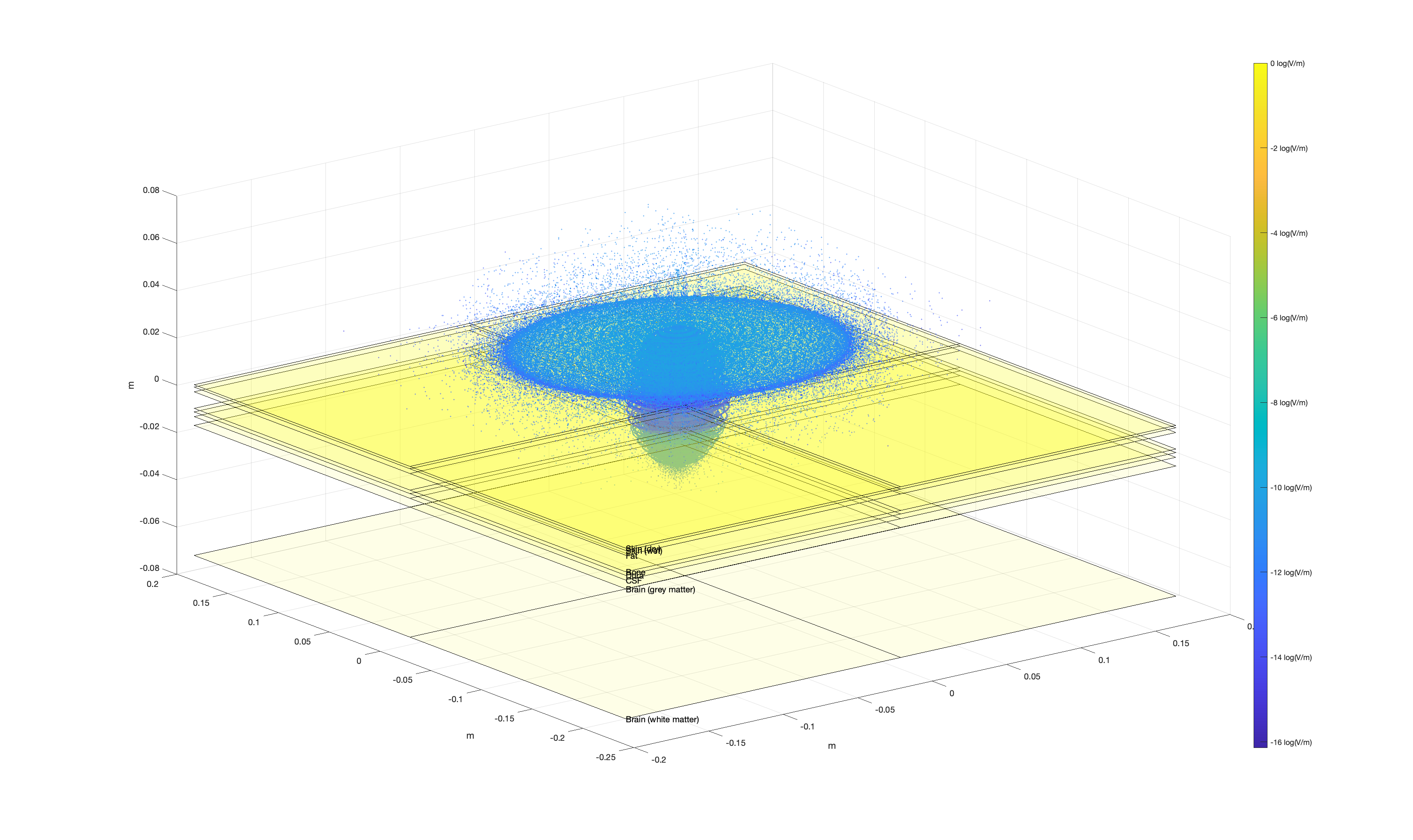


SAR analysis
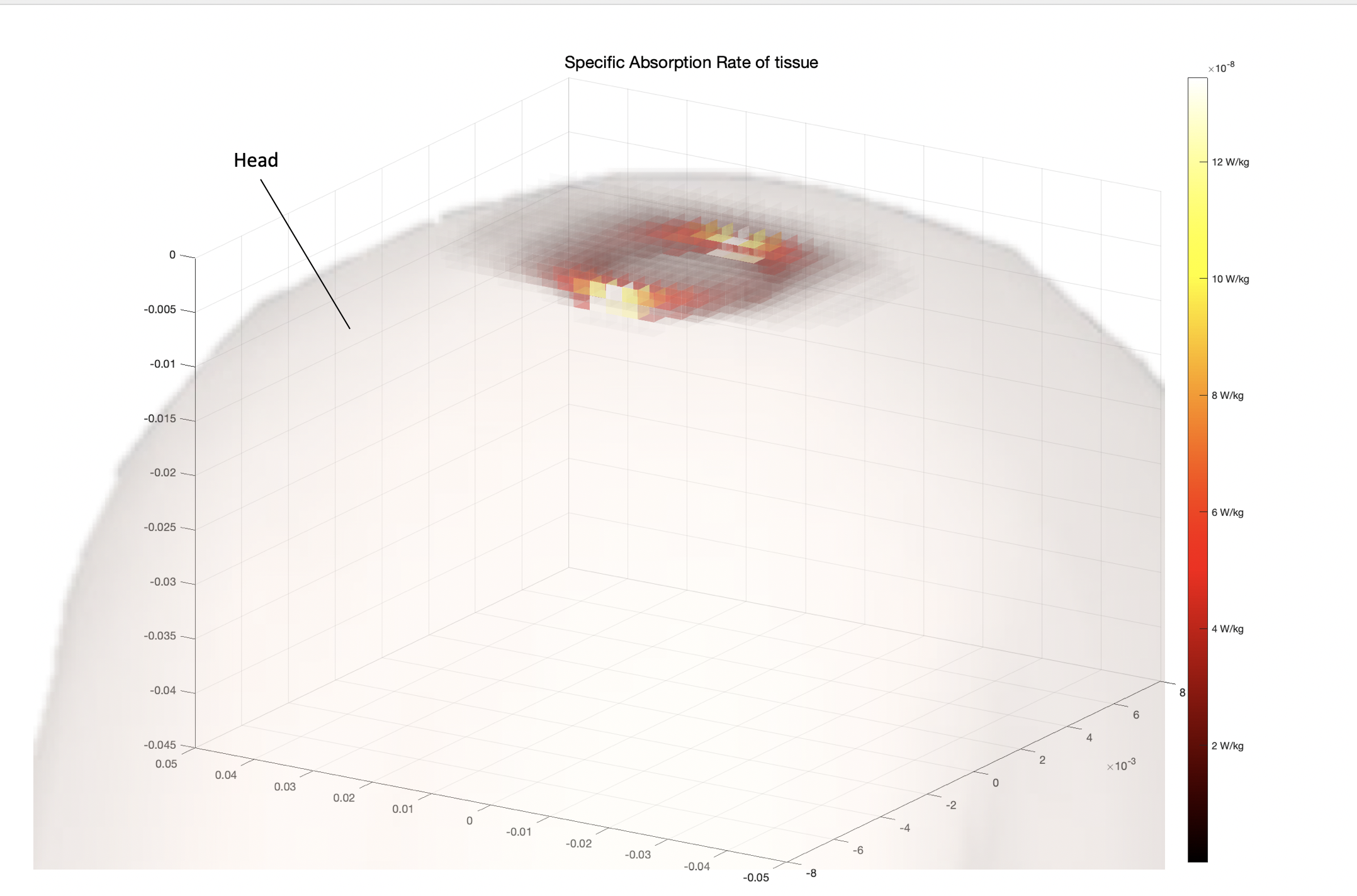
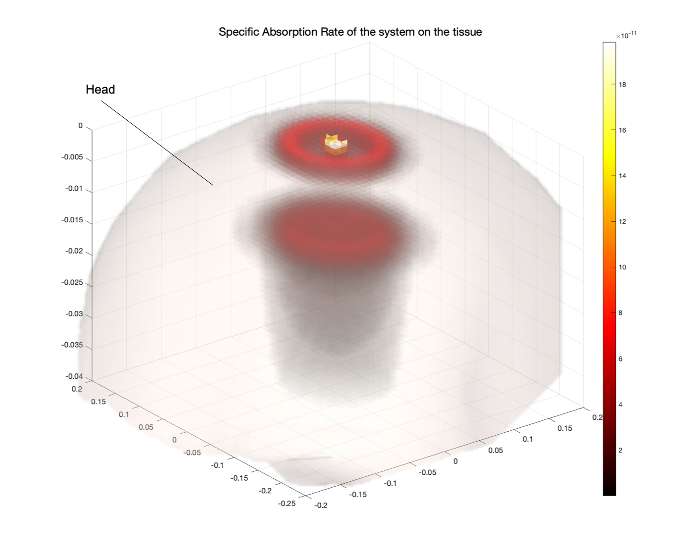
To simulate the Specific Absorption Rate of the transmitter antenna I wrote a MATLAB code that given a set of 3 antenna designs realized with the Antenna Toolbox extracts the gain, power and electric field of the antenna and simulates the intensity of the electric field through the different tissue layers of the head and the absorption rate in W/Kg to make sure that the tissue heating follows FCC regulations (<1.6 W/Kg).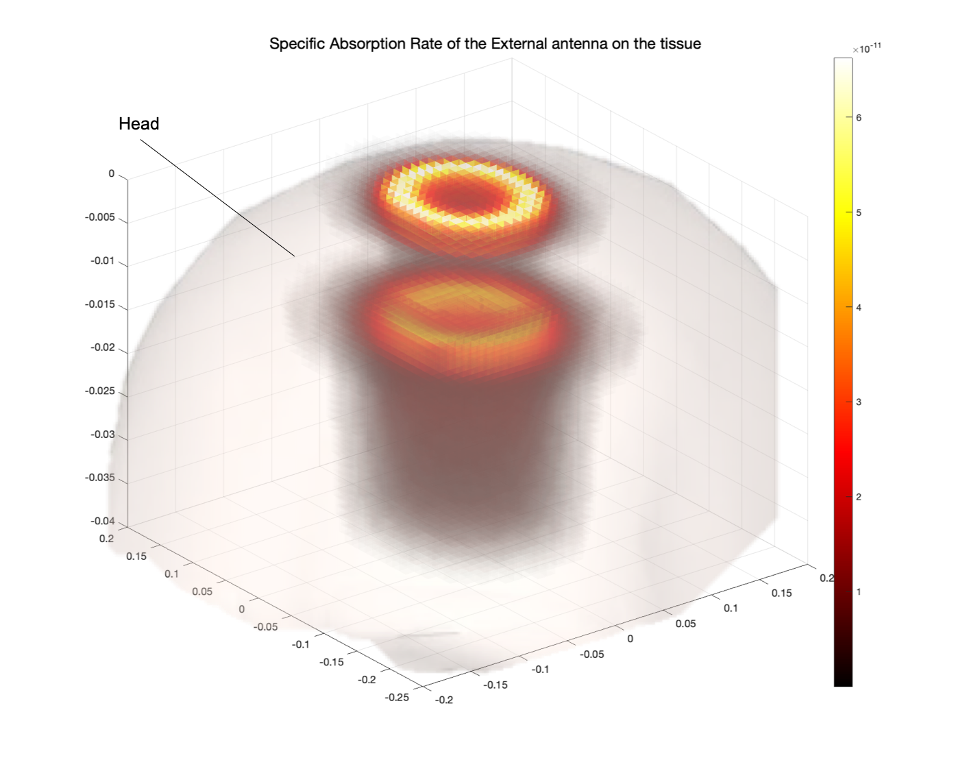

Wireless module architecture
The wireless module was designed with the idea of using backscattering to send information to the external system continuously. In this way less power would be consumed to communicate between the devices and there wouldn’t be the need to use packaged data as well as big on chip storage for the data.
When the data is received from the ADC converter it is first encoded through a Miller Encoder to separate correctly each value in an efficient way that is quick, easy and doesn’t occupy excessive bandwidth compared to other encoding methods such as Manchester. The encoded information is then sent to the ASK (Amplitude Shift Keying) modulator which converts the bits into variations of amplitude in the signal which is then sent out through the implanted antenna.
On the receiver side, the signal is received by the external antenna and separated from the sent-out power from a directional coupler. The data received is then amplified, passed to the mixer and filtered to remove frequencies above and below the frequency range of interest (considering a bandwidth of 10 MHz, 401 MHz – 411 MHz). Finally, the signal is decoded and sent to an ADC which converts it to digital signal.
Team members
The project was performed with:- Mitch Tang
-
Fan Yang
- Zhiyu Zhang
