A flow cytometer in a pocket
Fall 2023
This was a class long project done as part of the class “Advanced Topics in microfabrication” that I took in Fall 2023 with Dr. Andreas Andreou and Dr. Jeff Wang.
The objective was to build using common microfabrication techniques in a clean room, a working flow cytometer on a chip from a silicon wafer. Flow cytometers are useful tools for cell counting and cell properties characterization.
The flow cytometer consists of three inlets and one outlet. The central inlet is designated for the sample, while the two side inlets introduce a carrier liquid. These carrier liquids are maintained under constant pressure, directing the sample liquid to the center and focusing it into a narrow stream as it flows through the cross-junction.
Beyond the cross-junction, a set of electrodes is present, where an electric field is applied. These fields align and channel the cells and samples passing through, making them easier to detect.
A laser is directed at the region near the focusing electrodes, activating fluorescent markers attached to the cells. This allows precise counting of cells and, in samples with multiple cell types, allows for targeted marking and measurement of each cell type’s concentration.
![]()
![]()
Traditionally flow cytometers can be bulky and costly however, using microfabrication, it is possible to mass produce these microfluidic flow cytometers reliably in a relatively cost-effectly way.
The objective was to build using common microfabrication techniques in a clean room, a working flow cytometer on a chip from a silicon wafer. Flow cytometers are useful tools for cell counting and cell properties characterization.
Design
The flow cytometer consists of three inlets and one outlet. The central inlet is designated for the sample, while the two side inlets introduce a carrier liquid. These carrier liquids are maintained under constant pressure, directing the sample liquid to the center and focusing it into a narrow stream as it flows through the cross-junction.
Beyond the cross-junction, a set of electrodes is present, where an electric field is applied. These fields align and channel the cells and samples passing through, making them easier to detect.
A laser is directed at the region near the focusing electrodes, activating fluorescent markers attached to the cells. This allows precise counting of cells and, in samples with multiple cell types, allows for targeted marking and measurement of each cell type’s concentration.


Traditionally flow cytometers can be bulky and costly however, using microfabrication, it is possible to mass produce these microfluidic flow cytometers reliably in a relatively cost-effectly way.
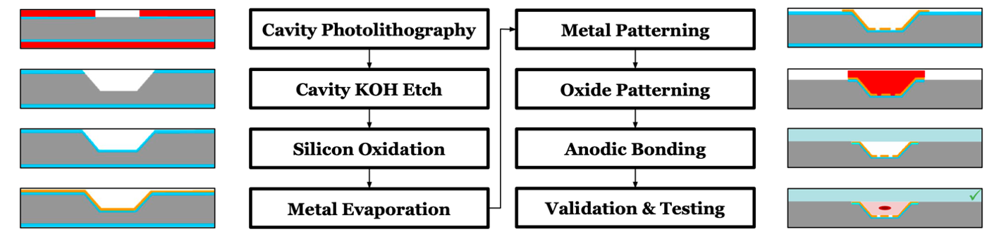
Process workflow
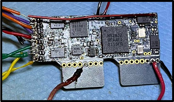
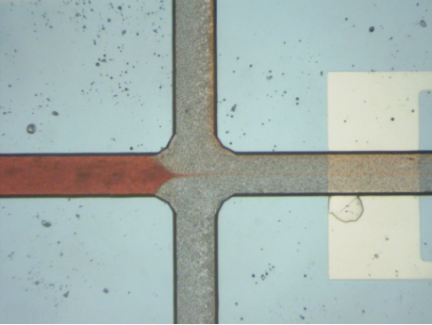
Final Device
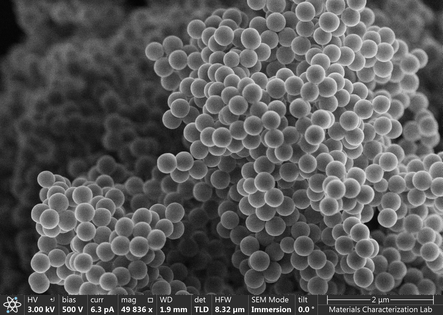
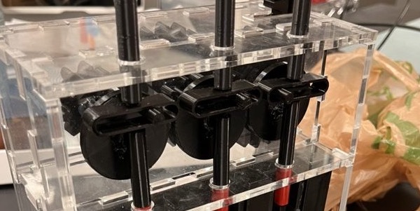
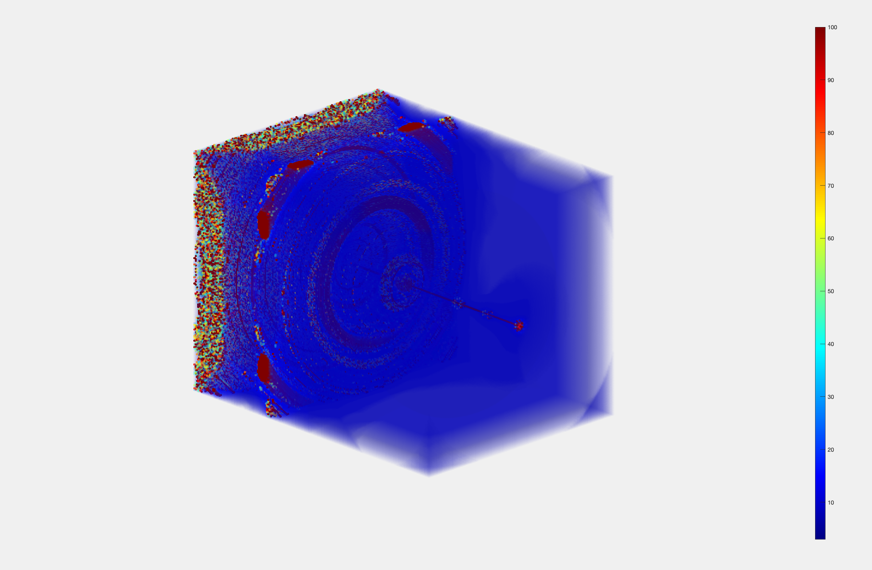
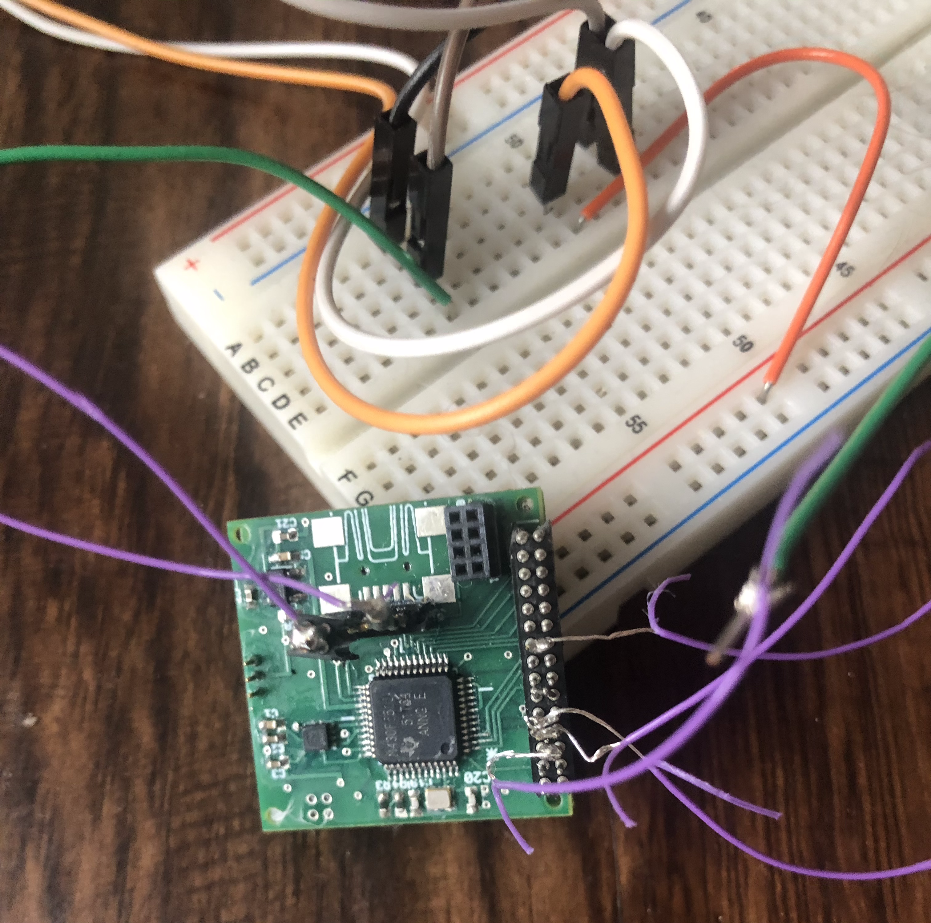
Below are the final results from the flow cytometer, fabricated using both PDMS and anodic bonding techniques. Both devices function effectively, as demonstrated by cross-junction testing on the cover (the result shown was the anodic bonding one).Using a surface profilometer, the channel morphology of the device was analyzed. Irregularities observed at the channel bottom are attributed to the rapid etching reaction between KOH and silicon. However, for the purposes of this project, high precision is not important, making these imperfections negligible.


If you are interested in a detailed report on this work, you can find it here.
Team members
The project was made with Max Kerensky and Ruixing Liang.Projects directory - Projects directory - Projects directory - Projects directory - Projects directory - Projects directory - Projects directory - Projects directory -