A compact magnonic sensor for brain biomagnetic studies
Fall 2023
This was another project I worked on during my first semester in Dr. Irazoqui’s lab.
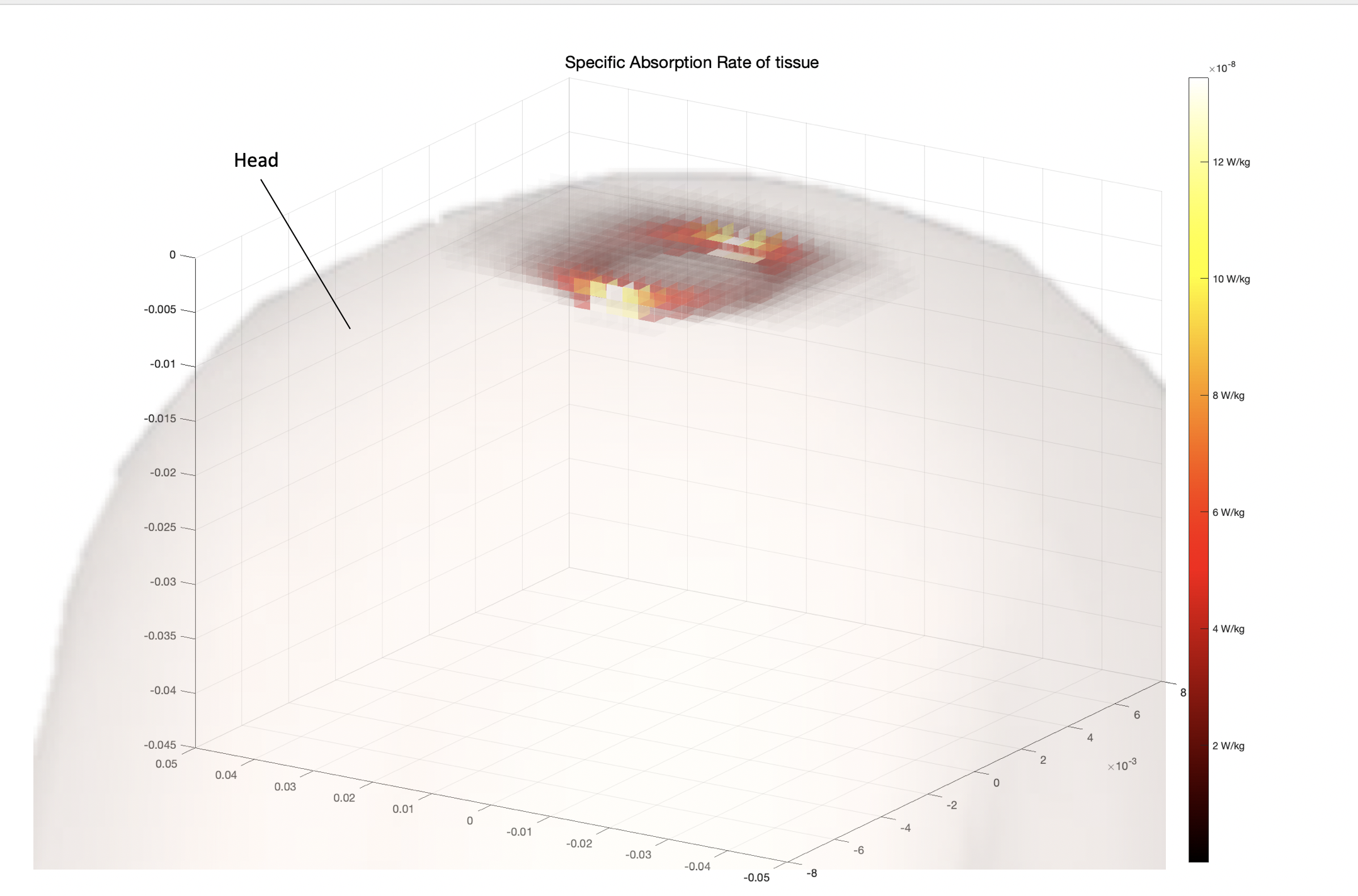
The objective was to build a more compact, economical and more precise magnetic sensor than SQUID. This was foreseen to be used for high density MEG recordings from deeper regions of the brain.
Working Principle and simulations
The working principle behind the functioning of this device relies on the use of magnons or spin waves. These are high frequency perturbations in the magnetization of a ferromagnetic material that propagate down the material. They are generally formed using antennas emitting the perturbation in a high strength magnetic field (depending on the properties of the gyromagnetic ratio of the ferromagnetic material) and they can be measured also using antennas by looking at their induced electromagnetic force.
![]() Magnetization Dynamics of a magnetic domain in a
ferromagnetic material, based on the Landau
Lifshitz Gilbert
equation.
Heff is
the external magnetic field while M the magnetization of a point on the material.
Magnetization Dynamics of a magnetic domain in a
ferromagnetic material, based on the Landau
Lifshitz Gilbert
equation.
Heff is
the external magnetic field while M the magnetization of a point on the material.
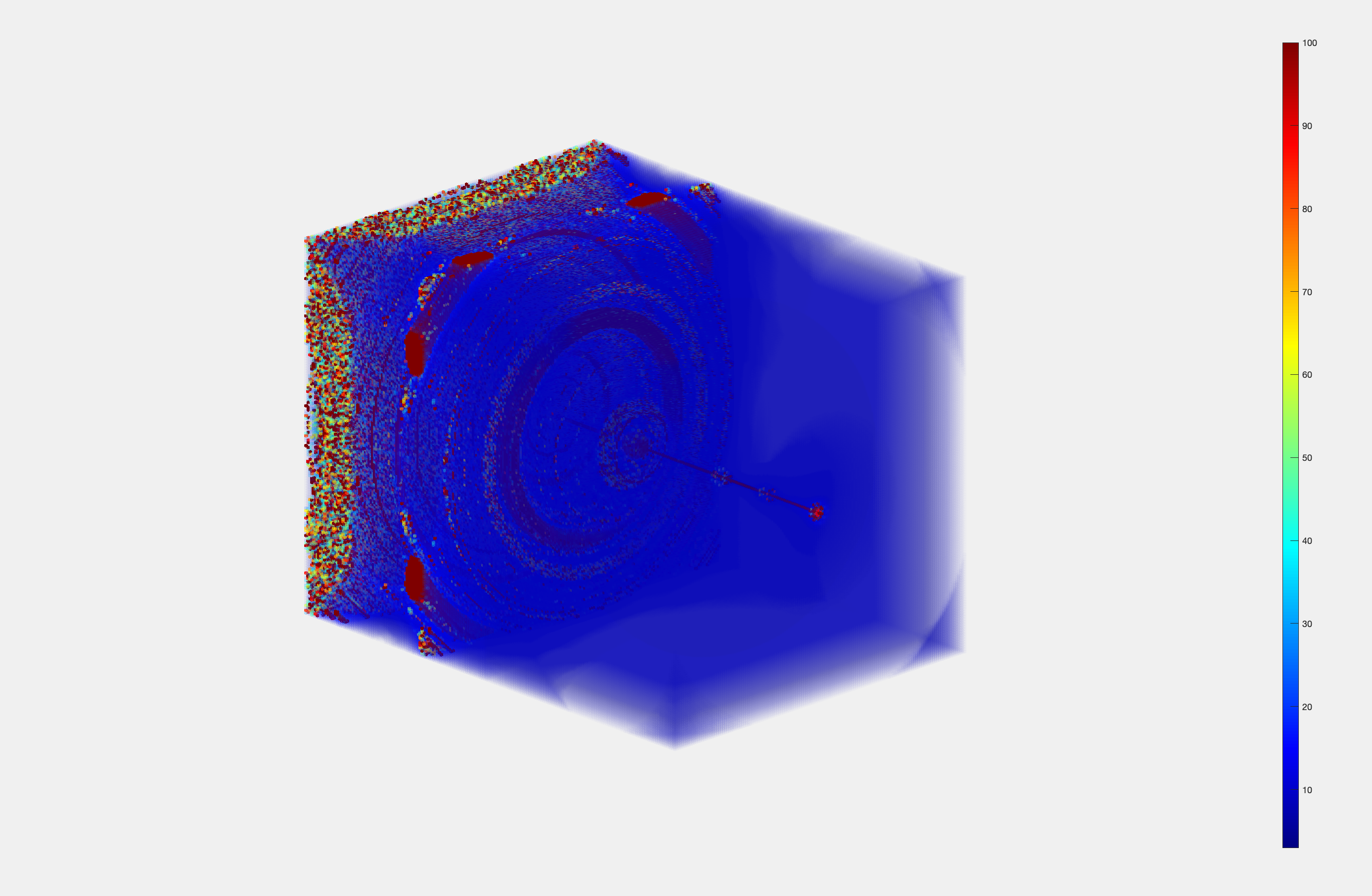
Based on the proof of concept from Balynsky (Balynsky, 2017), magnons can interfere as regular electromagnetic waves by using a cross junction. They can also be affected by small changes in external magnetic field, changing their phase and thus their interference. In very stable materials such as Yttrium Iron Garnet (YIG) where the spin waves propagate for centimeters, this can be used to measure very small magnetic fields with very low levels of noise, depending on the sensitivity of the antennas and the precision in measuring their phase. This can also be shown with a MATLAB simulation using the
Landau Lifshitz
Gilbert model.
![]()
![]()
![]()
Citation
- Balynsky, M., et al. "A magnetometer based on a spin wave interferometer." Scientific Reports 7.1 (2017): 11539.
- Walker, W.D. “Sub-Microdegree Phase Measurement Technique Using Lock-in Amplifiers.” IEEE International Frequency Control Symposium. IEEE, (2008). 825–828.
The objective was to build a more compact, economical and more precise magnetic sensor than SQUID. This was foreseen to be used for high density MEG recordings from deeper regions of the brain.
Working Principle and simulations
The working principle behind the functioning of this device relies on the use of magnons or spin waves. These are high frequency perturbations in the magnetization of a ferromagnetic material that propagate down the material. They are generally formed using antennas emitting the perturbation in a high strength magnetic field (depending on the properties of the gyromagnetic ratio of the ferromagnetic material) and they can be measured also using antennas by looking at their induced electromagnetic force. Magnetization Dynamics of a magnetic domain in a
ferromagnetic material, based on the Landau
Lifshitz Gilbert
equation.
Heff is
the external magnetic field while M the magnetization of a point on the material.
Magnetization Dynamics of a magnetic domain in a
ferromagnetic material, based on the Landau
Lifshitz Gilbert
equation.
Heff is
the external magnetic field while M the magnetization of a point on the material.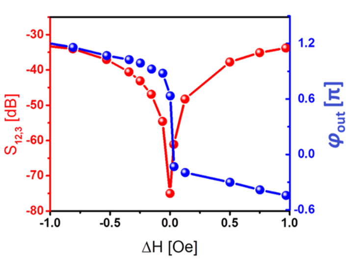
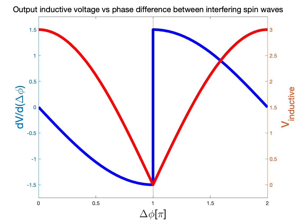
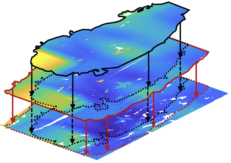
Simulated output of inducted voltage based on the
phase difference between spin waves (red line) and the phase read (blue line) and experimental data (Balynsky,2017)
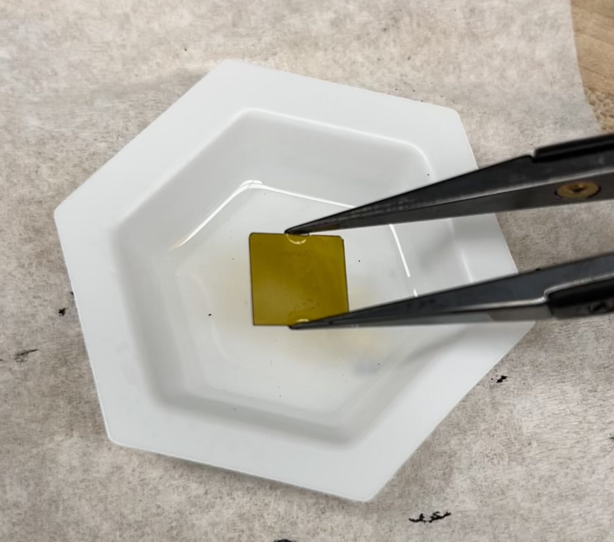
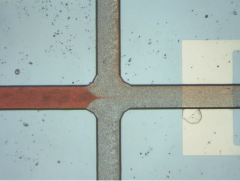
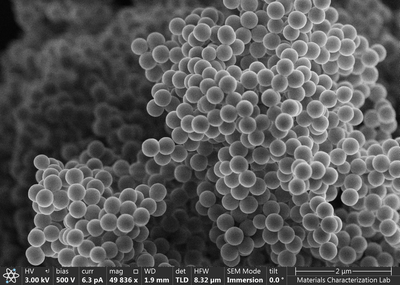
YIG sample that we bought for the device. 1 cm x 1 cm.
Citation
- Balynsky, M., et al. "A magnetometer based on a spin wave interferometer." Scientific Reports 7.1 (2017): 11539.
- Walker, W.D. “Sub-Microdegree Phase Measurement Technique Using Lock-in Amplifiers.” IEEE International Frequency Control Symposium. IEEE, (2008). 825–828.
Device circuitry and design
Reading the change in phase after the cross junction is then key to measuring magnetic fields at very small changes. This not only can tell the intensity of the field, but in a cross junction provides the 2D vector of the field, element never obtained from current high precision devices. Given the importance of the phase, we decided to implement a lock-in amplifier and use a technique of phase amplification (Walker, 2008) that subtracts the original signal from the recorded one. 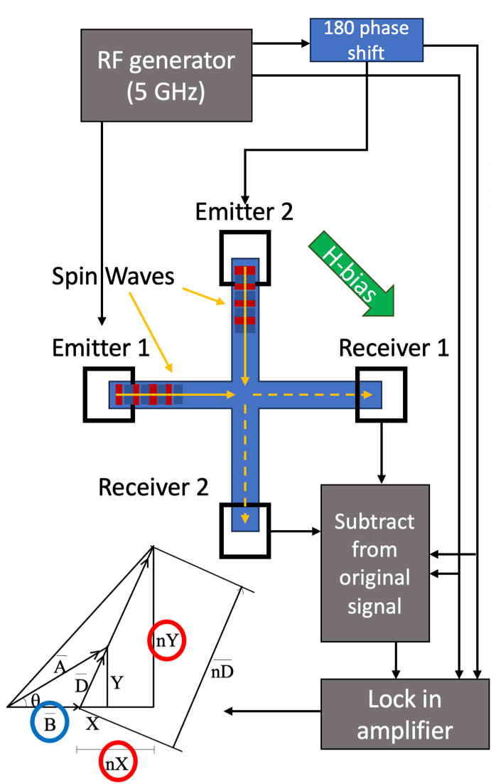
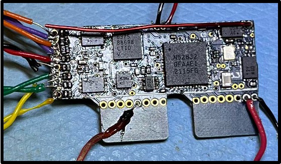
Schematics of the magnetic sensor design. The RF
generator produces a 5GHz signal (B) which is used to generate the spin waves
in the cross junction. As the spin waves interfere at the center, they move to
the receiver where they are read by two antennas. From the original signal (B)
the reading (A) is subtracted forming D. We then pass D through a lock in
amplifier to extract its coordinates amplified (nX and nY) from which the phase (phi) can be estimated.
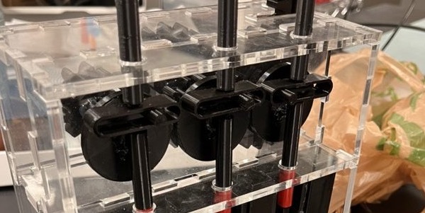
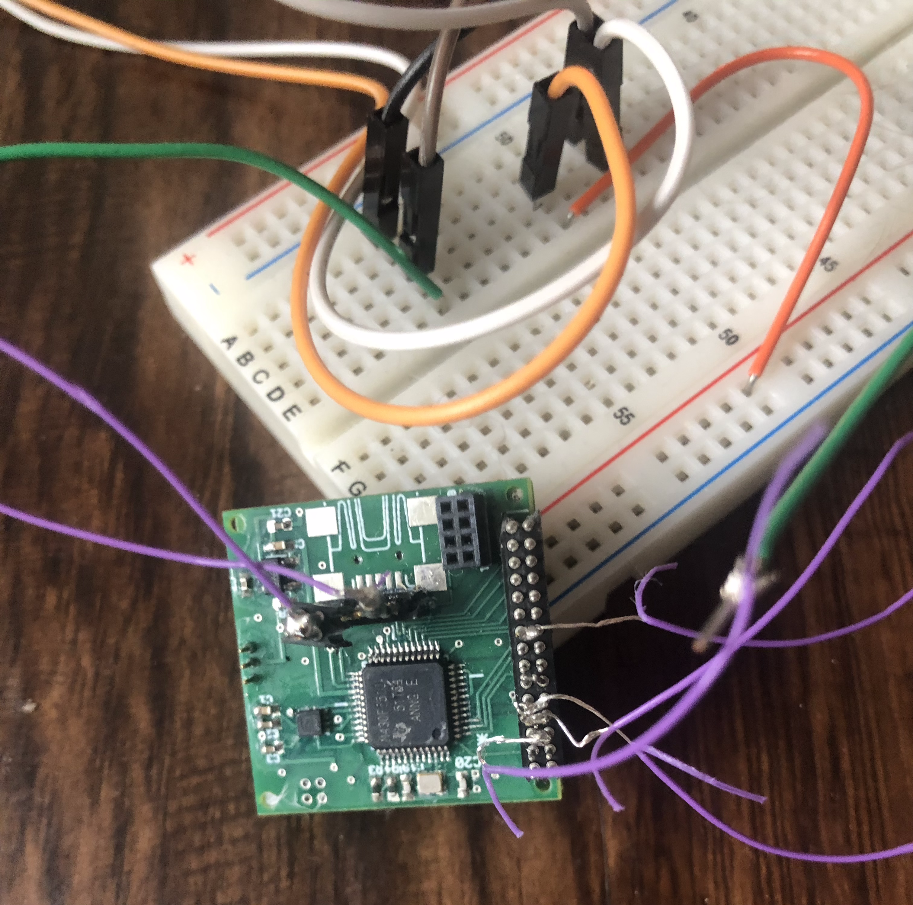
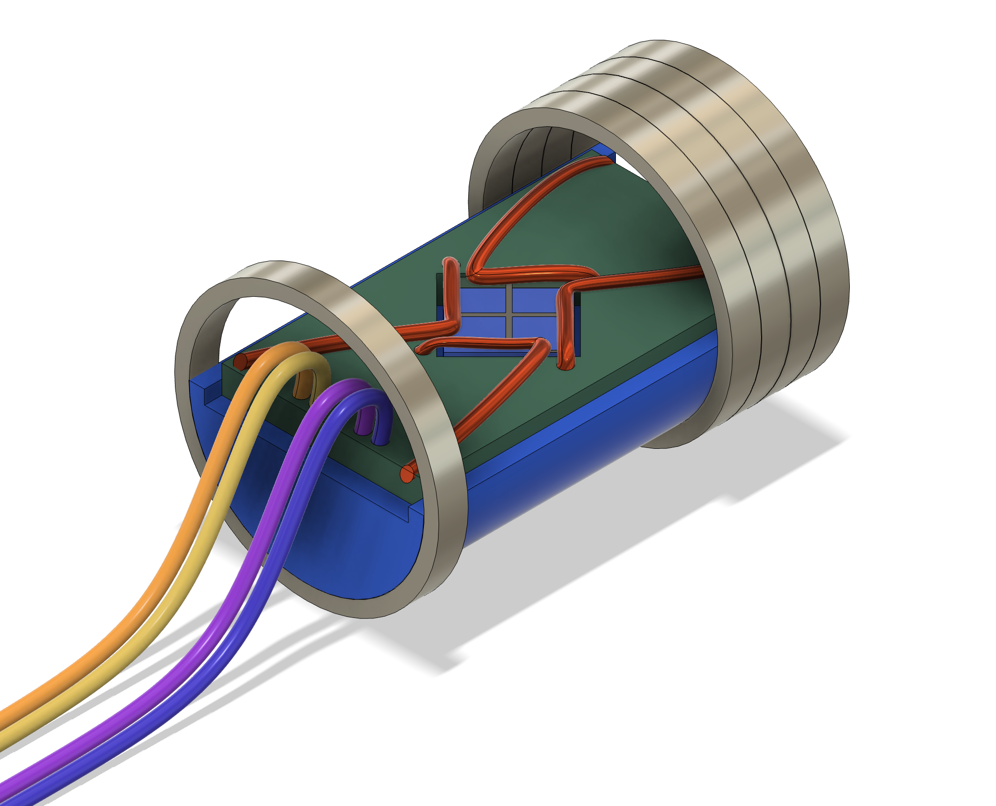
Experimental design

Limitations
The project despite exciting faced several limitations (mostly related to the precision of the electronics) that didn’t permit it’s advancement beyond theoretical design:- High frequency precision - Finding compact IC that could emit synchronously and precisely 5 GHz signals revealed itself to be quite the challenge. Often these are reserved for RF however when multiple are required, even small drifting in one of the emitters can make the device not work properly
- Strong magnetic fields - The gyromagnetic ratio of the device required for 5GHz frequency a field of about 1 T (higher frequencies require higher fields). This is challenging to achieve and permanent magnets might be needed. However, small fluctuations in environment temperature can affect the magnetic field, affecting the resonant frequency of the device and the recordings.
Projects directory - Projects directory - Projects directory - Projects directory - Projects directory - Projects directory - Projects directory - Projects directory -